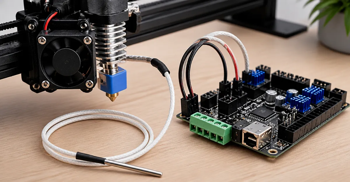
Introduction
This guide explains how one can install an E3D PT100 temperature sensor on a BigTreeTech SKR control board, wire the sensor securely, adjust Marlin firmware settings, and perform a reliable calibration. Accurate temperature measurement is essential for maintaining melt‑zone stability, preventing filament degradation, and achieving consistent print quality. By following the procedures outlined herein, one will gain confidence in integrating a high‑precision RTD sensor into a modern 3D printer ecosystem.
What You'll Need
- Jaybva PT100 Temperature Sensor – 3‑wire waterproof probe, 2 m shielded cable, A‑grade accuracy, $13.98, rating 4.5/5.
- Jaybva PT100 Temp Sensor – Compact 6.6‑ft PFA cable, stainless‑steel 304 body, $12.98, rating 4.6/5.
- T‑PRO PT100 Temperature Sensor – 10‑ft PFA cable, stainless‑steel 316, $14.99, rating 4.4/5.
- Ultimaker 2 PT100 Sensor Cable – 1.4 m cable with m3×15 mm connector, $14.99, rating 4/5.
- BigTreeTech SKR board (v1.4 or later) with available 3‑wire RTD input pins.
- MAX31865 RTD amplifier board (compatible with 3‑wire PT100).
- Screwdriver set, heat‑shrink tubing, soldering iron, and multimeter.
- Marlin firmware source (version 2.0 or newer) and a computer for compilation.
Step 1 – Prepare the Sensor and Cable
Begin by selecting a PT100 probe that matches the temperature range of the hotend. The Jaybva PT100 Temperature Sensor offers a broad range of -50 °C to 500 °C and a robust 2 m shielded cable, making it suitable for high‑temperature extruders. Its stainless‑steel 304 construction resists corrosion, and the A‑grade accuracy ensures temperature readings within ±0.15 °C. Carefully inspect the cable for kinks; the braided shield provides electromagnetic interference protection but can become fragile if sharply bent.
If space constraints exist inside the printer chassis, the shorter Jaybva PT100 Temp Sensor (6.6 ft) may be preferable. Its PFA jacket offers excellent chemical resistance and flexibility, allowing easy routing through tight cable channels.
For installations that require a longer run, the T‑PRO PT100 Temperature Sensor provides a 10‑ft cable and a grease‑proof stainless‑steel 316 body, which is advantageous in environments with frequent filament changes.
Step 2 – Attach the MAX31865 Amplifier
The SKR board does not read raw RTD resistance directly; an external amplifier such as the MAX31865 is required. Connect the three wires of the chosen PT100 probe to the amplifier as follows: red to the + terminal, blue to the – terminal, and the second blue (or black) to the sense terminal. The shielded cable should be stripped only at the termination points to preserve its noise‑reduction properties.
Secure the connections with solder and heat‑shrink tubing. Verify continuity with a multimeter: the resistance between the two sense leads should read approximately 100 Ω at 0 °C. A proper connection will prevent the “sensor error” messages that can appear during printing.
Step 3 – Wire the Amplifier to the SKR Board
Locate the SPI pins on the SKR board (MISO, MOSI, SCK, and CS). The MAX31865 uses SPI communication, so connect its CS pin to an available GPIO (for example, PA4), MOSI to the board’s MOSI pin, MISO to MISO, and SCK to SCK. Power the amplifier from the 3.3 V rail; the sensor itself operates at the voltage supplied by the amplifier, typically 3.3 V.
When a direct connector is desired, the Ultimaker 2 PT100 Sensor Cable can serve as a ready‑made interface. Its m3×15 mm cartridge fits many hotend blocks, and the 1.4 m length matches the typical distance between the extruder and the controller board. Note that this cable is designed for Ultimaker printers; one must replace the proprietary connector with a standard Dupont or JST header to mate with the SKR board.
Step 4 – Configure Marlin Firmware
Open the Marlin configuration files (Configuration.h and Configuration_adv.h). Enable the PT100 sensor type by setting:
#define TEMP_SENSOR_0 20 // 20 corresponds to PT100 with MAX31865
Next, define the SPI pins for the sensor in pins_BTT_SKR_V1_4.h (or the appropriate board file):
#define TEMP_0_CS_PIN    PA4
#define TEMP_0_SCK_PIN   PA5
#define TEMP_0_MISO_PIN  PA6
#define TEMP_0_MOSI_PIN  PA7
Adjust the temperature oversampling to improve stability:
#define TEMP_OVERSAMPLING 16
Re‑compile the firmware using PlatformIO or Arduino IDE, then upload the binary to the SKR board via USB or SD card. After flashing, the printer will display temperature readings from the PT100 sensor.
Step 5 – Calibrate the Sensor
Calibration ensures that the firmware’s temperature conversion matches the physical reality of the hotend. Begin by heating the nozzle to a known temperature, such as 200 °C, using a calibrated external thermometer (e.g., a mercury‑in‑glass reference). Compare the Marlin readout with the reference. If a discrepancy exists, adjust the temperature offset in Configuration.h:
#define TEMP_SENSOR_0_OFFSET 0 // adjust in 0.1 °C steps
Iterate the process at multiple set points (e.g., 180 °C, 220 °C) to achieve linearity across the operating range. Record the final offset values for future reference.
Tips & Pro Tips
- Use heat‑shrink tubing on all solder joints to protect against filament debris and moisture.
- When routing the cable, maintain a minimum bend radius of 5 mm to avoid damaging the shielded wire.
- Prefer A‑grade PT100 sensors (such as the Jaybva models) for applications where temperature precision directly influences part strength.
- Store spare PT100 probes in a dry environment; prolonged exposure to humidity can degrade the waterproof sealing.
- If the printer firmware does not support native RTD reading, an external Arduino or ESP32 can act as a bridge, sending calibrated temperature data via UART.
Troubleshooting
| Problem | Possible Cause | Solution |
|---|---|---|
| Sensor reports 0 °C constantly | Incorrect wiring of the three‑wire RTD | Verify that the red lead connects to +, the blue leads to – and sense; re‑solder if necessary. |
| Temperature fluctuates wildly | Loose connector on the MAX31865 | Secure the connector, apply heat‑shrink, and ensure the SPI CS pin is stable. |
| Marlin does not recognize PT100 | Incorrect sensor type constant | Set TEMP_SENSOR_0 to 20 and re‑compile firmware. |
| Over‑temperature error after a few prints | Amplifier overheating | Provide adequate airflow over the MAX31865 board or relocate it away from the hotend. |
Conclusion
By following the steps above, one can successfully install an E3D PT100 sensor on a BigTreeTech SKR board, achieve accurate temperature reporting, and calibrate the system for optimal print performance. The combination of a high‑quality PT100 probe, a reliable MAX31865 amplifier, and correctly configured Marlin firmware provides a robust solution for advanced 3D printing applications.
Products Mentioned in This Guide
Frequently Asked Questions
How do I wire a 3‑wire PT100 sensor to a BigTreeTech SKR board?
Connect the sensor’s three wires to the SKR’s PT100 pins (or via a MAX31865 breakout) according to the board’s schematic and ground the shield for noise reduction.
Which Marlin firmware settings must be changed for a PT100 sensor?
Enable PT100 by setting the appropriate TEMP_SENSOR index (e.g., TEMP_SENSOR_0 1) and configure PT100_RESISTANCE and gain values, optionally activating the MAX31865 module.
What is the recommended method for calibrating the PT100 on an SKR board?
Heat the hot‑end to a known temperature, compare it with a calibrated thermometer, and adjust Marlin’s PID and temperature offset values using M303 or the firmware’s calibration menu.
Can I use a waterproof PT100 probe with a 6.6‑ft or 10‑ft cable on the SKR board?
Yes, both cable lengths work; just account for the extra cable resistance in the PT100_RESISTANCE setting to maintain accuracy.
What are the benefits of using a PT100 sensor over a thermistor in 3D printing?
PT100 offers a linear response, higher precision, and better stability at high temperatures, reducing filament degradation and improving print quality.